Adding the device
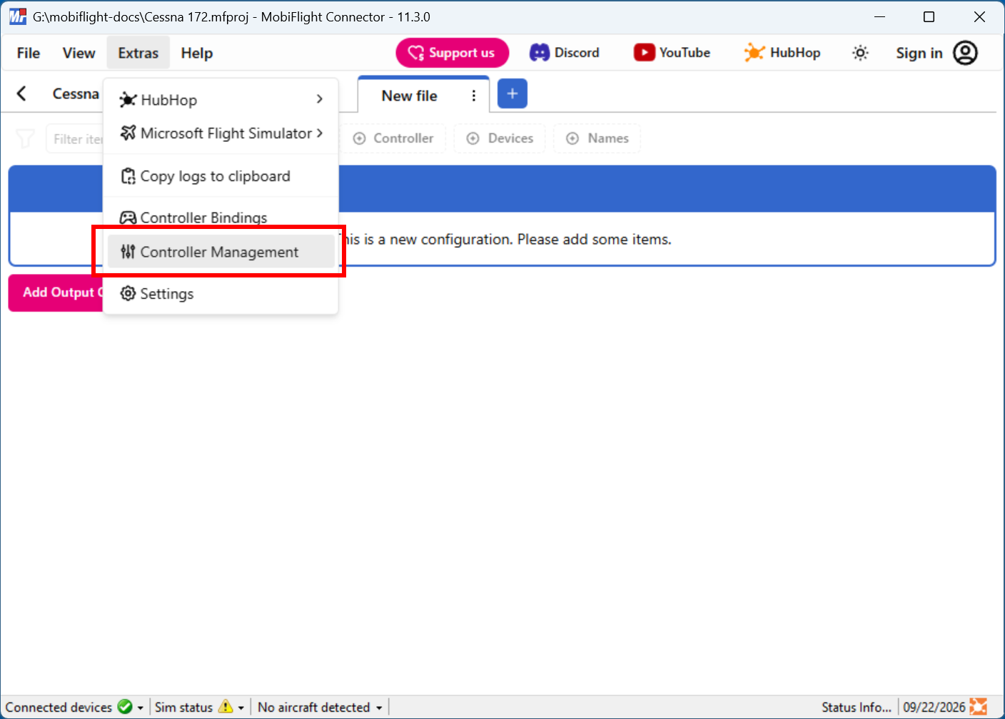
Open the Controller Management dialog
Click on the Extras menu and select Controller Management to open the Controller Management dialog.
Add the LCD
Click on the board the device is connected to, then select LCD Display from the Add device menu.

Configure the display
Use the Display settings to set the address for the display. Use the Columns and Lines fields to specify the number of columns and rows for the connected display.
Provide a meaningful name for the display in the Name field. This name is shown in the output configuration screens when assigning the display to flight simulator outputs.
Tip
Most displays have a default address of 0x27. To change the display address, solder resistors to the available A0–A2 pads on the driver board.

Upload the changes to the board
Click the Upload config button at the bottom of the MobiFlight Modules tab to upload the modified configuration to the board.

Close the MobiFlight modules dialog
Click the OK button to close the MobiFlight modules dialog and return to the main app window.